
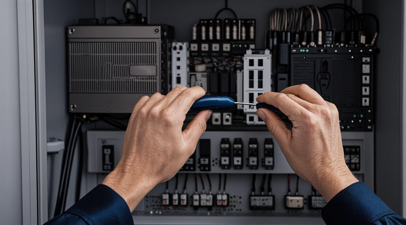
Keep three wiring groups separate: line input to the power terminals, motor output to U/V/W, and protective earth (PE). Use a shielded motor cable grounded at both ends, route control wiring away from power cables, and never install capacitors or unloaded switching devices between the drive and the motor.
Which terminals are which?
Power terminals divide into three groups. The line input connects to L1/L2/L3 (marked R/S/T in some manuals), the motor connects to U/V/W, and PE bonds the drive chassis to the cabinet ground. Control terminals sit separately: digital inputs for start/stop and forward/reverse, an analog input for speed reference, relay or digital outputs for status, and RS-485 for Modbus. On models like the Qingtian EC590, the exact layout is shown for each frame in the quick guide — download the current version before wiring.
One check saves a drive: confirm the motor is on the output terminals, not the input. Reversing input and output destroys the output stage instantly at power-up.
A typical EC590 terminal-start setup
Most machinery only needs terminal start/stop and an external speed reference. These examples follow the EC590 application wiring guide — always verify parameter codes against the quick guide version shipped with your drive.
| Setup | Wiring | EC590 parameters |
|---|---|---|
| Terminal run/stop, keypad potentiometer speed | Run switch between S1 and COM | F0-02=1, F0-03=1 |
| Terminal run/stop, external 0–10 V speed | S1–COM run, 0–10 V signal to the analog input | F0-02=1, F0-03=2 |
| Forward and reverse from terminals | S1 forward, S2 reverse (each against COM) | F0-02=1, F4-01=2 |
| 4–20 mA speed reference | Transmitter current loop to the analog input | F0-02=1, F0-03=3, F4-40=2 |
What cable should you use between drive and motor?
Use a shielded motor cable with a continuous shield, cross-section matched to the motor’s full-load current, and 360° shield clamping at both the drive gland and the motor terminal box. Route motor power away from control and signal cables — where crossing is unavoidable, cross at 90°. Long cable runs raise reflected voltage at the motor terminals and conducted interference; once a run exceeds the quick guide’s guidance for your frame, add an output reactor or dv/dt filter. If you are unsure, tell us the cable length and we will confirm what your frame needs.
How do you ground a VFD correctly?
- Connect PE to a dedicated grounding bus with low impedance — never through paint or anodizing; scrape a clean contact area.
- Ground the motor cable shield at both the drive end and the motor end.
- Keep signal ground separate from power ground and join them at a single point as described in the manual.
- Do not use the drive’s PE terminal as a junction for other high-current equipment grounds.
Five wiring mistakes that damage drives
- Installing power factor correction capacitors between the drive and the motor — this destroys the output stage.
- Switching a contactor between the drive and the motor while running — voltage spikes stress the insulation. If a contactor is unavoidable, interlock it and operate it only when the drive output is stopped.
- Connecting the motor to the input terminals — an instant failure at power-up.
- Running unscreened motor cable bundled with control and signal wiring — electromagnetic interference causes nuisance trips in nearby electronics.
- Grounding through painted surfaces or long, thin PE wires — high-impedance grounding defeats the built-in filter and protection design.
Safe first power-up sequence
- De-energize, lock out and tag the cabinet, then verify zero voltage.
- Confirm every power terminal is tightened to torque and the phases are correct.
- Test motor insulation with the motor disconnected from the drive — never megger through a connected drive.
- Power up with the motor uncoupled or unloaded and enter the motor nameplate data: FLA, rated frequency and rated speed.
- Run a low-frequency ramp test, verify rotation direction, then load the machine gradually.
Need the parameter list or a machine-specific diagram? Download the EC590 and EC6000 guides or send us your application details — our engineers answer within 24 hours on business days.
FAQ
Can I install a contactor between the VFD and the motor?
Avoid it where possible — start and stop through the drive’s control terminals. If your design requires an output contactor, interlock it so it only opens and closes when the drive output is stopped, and never use it as an emergency stop.
How long can the motor cable be?
It depends on the drive frame and switching frequency. Long unscreened cables increase reflected voltage at the motor and conducted interference. Stay within the quick guide’s limit for your model, and send us your run length — we will confirm whether an output reactor or dv/dt filter is needed.
Where can I get wiring diagrams?
The EC590 and EC6000 quick guides on our downloads page cover terminal layouts and parameter codes. For machine-specific diagrams, describe your application through the contact form.